Everything You Need to Know about Aircraft Electrical in 1,000 Words (more or less)
By Jim Cavanagh
Naturally, we can’t be expected to know everything about our airplanes. After all, that’s why we have mechanics, right? As an aircraft owner and writer, I’ve devoted years of work to familiarizing pilots and owners with the basics of how and why our airplanes work. While some of us simply enjoy working on our birds as part of the hobby aspect of flying, there are others who don’t necessarily want to get their hands dirty. Still, all of us can benefit from fundamental systems knowledge, especially when it comes to telling your mechanic about a problem so that he or she can better understand it and work more efficiently to troubleshoot and repair that problem. Some of these systems are easier to understand than others, but one system that has many owners flummoxed is the electrical system.
Let’s forget about mags for a second. All airplanes have them and they are independent of the electrical system. I once lost an alternator and finished a flight by flying a Grumman Tiger like a Piper Cub for 600 miles. Piece of cake—it called for different skills, but it was cool! But if you have a starter, and if you have a radio, then you will need an electrical system on board.
This discussion will tell you how an aircraft electrical system works, not why. We don’t want to teach electrical engineering here, rather create an understanding of the basic system.
Our electrical systems are pretty simple. We use DC power in our airplanes (and, for that matter, most other vehicles) as opposed to AC which we use in our houses. We do this because the wire gauge can be much smaller (for weight and space considerations), the voltage is much lower, thus safer, and because the energy is “quieter.” DC current flows in a straight line and is also called Constant Current, as there are no fluctuations in the current value. The main components of our system are a battery, an alternator or generator, a master solenoid, a master switch, a buss bar, wire, switches and, finally, the appliances.
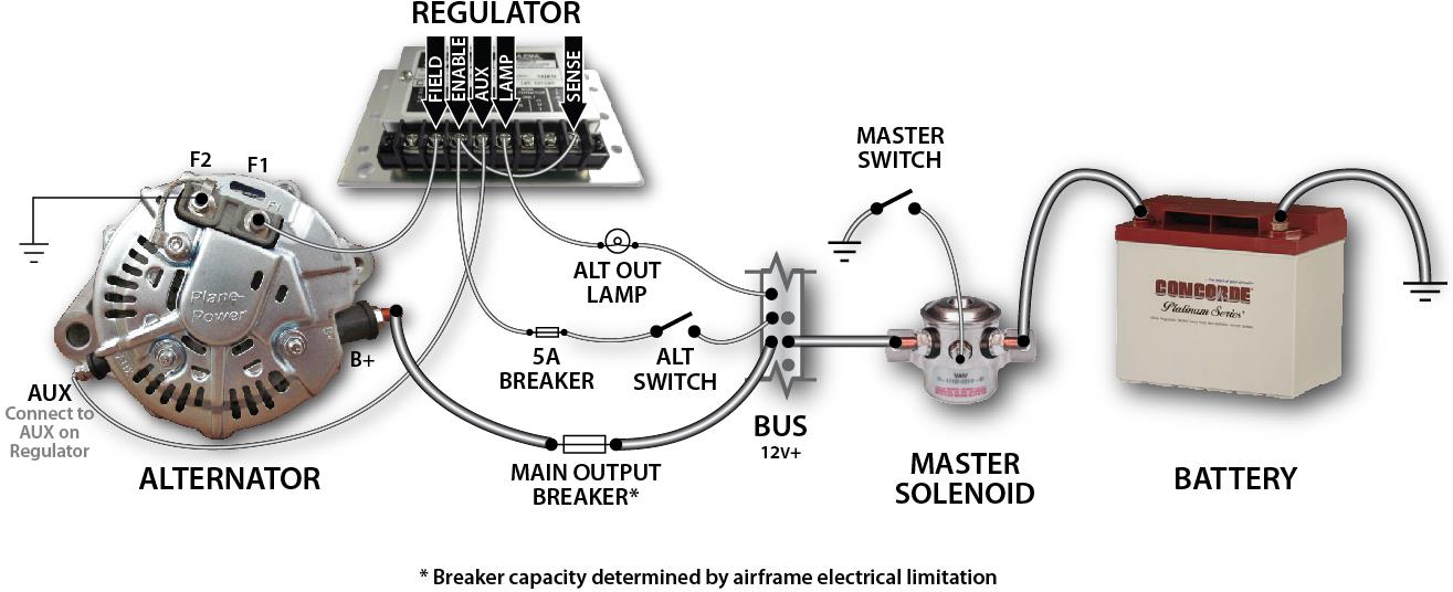
Older aircraft were built with generators that produced DC current. Generators suffered from high weight, unreliability, and their output was directly tied to the RPMs of the engine. At idle or low RPM, demand on the battery could cause it to run out of power. Alternators were simpler, lighter, cheaper, and much more dependable. They create AC current that is rectified into DC. In fact, Plane Power (www.plane-power.com), an alternator manufacturer in Texas, builds a 150-amp alternator that weighs less than an old 40-amp generator.
Today’s aircraft have two different systems: 14-volt and 28-volt. The 28-volt systems use even lighter wiring and lighting, and appliances are designed differently so nothing is interchangeable. The downside of a 28-volt system is the expense of the battery—which didn’t seem to bother the designers. In this piece, we’ll concentrate on 14-volt systems, though the theory is the same for both.
The power source in our airplanes is the battery. Most batteries are lead acid; though lithium and nickel cadmium batteries are becoming more popular. The positive side of the battery (cathode) is connected directly to the master solenoid and the alternator. The negative side (anode) of the battery is connected to the airframe and engine. A solenoid is a switch that’s capable of handling a large amount of power, but may be controlled by a very small amount of power. Located strategically, solenoids can save a lot of wire weight. The right side of the master switch provides the connection to ground that closes the contactors in the solenoid. This completes the circuit to the buss (named after the founder of Buss Fuses, years ago) and the airplane is powered up. The left side of the master switch provides 5-amp power to energize the alternator. The switch is split to separate the two systems.
Aircraft wiring usually consists of tin-coated copper-stranded wire covered by insulation. Until the early 90’s, wire was insulated with PVC, but it has since been phased out and replaced with Tefzel. Some wires are also reinforced with nylon. OEM wiring is usually coded about every six to twelve inches. Your Maintenance manual will have a list of the wiring codes’ corresponding circuits. This makes it much easier to track down a problem in a thick bundle. Heavier wire is used for high-demand motors, pumps, and some lighting. With LEDs and newer electronics requiring much less power, older wiring can be used for new installation as it usually has far more capacity than needed. Wire, individually or in bundles, has to be secured where practical, and bundles must be tied around every four to six inches. Both have to be protected from chafing by space or mechanical means.
All electrical systems require power and ground. Electrical energy travels from the power source through the electrical buss bar, a heavier solid piece of metal to which a number of spaces are devoted to breakers or fuses. Breakers/fuses are used to control the power to an appliance. They are matched to the wiring size for a particular appliance, based on its energy requirement. When a fault develops, like a short or a burned out component, the power either wants to flow freely and immediately to ground or there is sufficient resistance to cause a heat buildup. This heat is what causes a breaker to “pop” or disengage or a fuse to “blow” or burn. Breakers allow instant control of a circuit and can be pulled or turned off and reset manually. Conversely, fuses must be replaced, and, if there are no extras onboard, you could be in a pickle.
Everything on an airplane that uses electrical power has a positive and a negative lead. An appliance is grounded by a separate lead attached to the airframe or fastened securely to a bracket on the airframe. Sometimes a grounding buss is used to keep all grounds together and neat. Grounding terminals are usually secured with a “star” washer for positive contact and to prevent the fastener from loosening. The positive lead is connected to power where the power line is attached. Power flows from the buss to the appliance, energizes the appliance, and then flows through ground back to the battery. When the circuit is closed (on) then the power is used by motors or whatever, and then flows to ground. An “open” circuit denotes a break in the electrical flow.
To this point, we have the battery through which all power is distributed to the airplane. Upstream of the battery is the alternator/generator that keeps the battery charged when the engine is running. The charge is controlled by the voltage regulator, and power is taken from the battery to two locations: the aircraft electrical buss and the starter solenoid. This solenoid is the HD switch that sends a huge amount of power to the starter. A position on the ignition switch closes the solenoid circuit to start cranking. NEVER crank an engine longer than ten seconds and ALWAYS wait twenty seconds before cranking again. You can do this up to five times. If it hasn’t started by then, give it 30 minutes to cool down or you risk causing damage.
A circuit is a line which provides power to a specific electrical accessory on the airplane. These circuits usually have values ranging from 5 to 20 amps on our smaller airplanes. On larger airplanes, there can be dozens designated for things such as lighting, pumps, instruments, radios, flaps, landing gear, and more. Different circuits require different amounts of power. Electric flaps are usually a high value, as is a cigar lighter (these days called a Power Port). On the other hand, instrument lighting has a rather small value. From these, it’s not unusual to have a one-off appliance that uses a small amount of power. This is usually protected by an inline fuse or another breaker mounted close to the item.
When you turn something on and it doesn’t come to life, the first thing you should do is glance at the breakers or check the fuses. If you find that one has blown, go to that particular circuit and look for the reason. A light bulb is fairly easy—unless, of course, there are a dozen or more lights on the circuit. Though one does not affect the other, a melted receptacle will short the system. Corrosion is also a huge problem, as is the dreaded mouse! Maybe Teflon tastes like cheese…I don’t know, but these guys love to chew on wires.
While you can do some electrical repairs yourself, you must have the correct tools, wire, and other components. FAR Part 43, Appendix A, Paragraph C—Preventive Maintenance lists what you can do—basically repair circuits and wiring to landing lights and replace components of other lighting circuits. The components must be approved, so don’t use auto store connectors and wire. An electrical load chart is usually found in the Maintenance Manual, along with the wiring schematic and the aforementioned wire sizes and codes. If you have to really dig into the system to add a component or replace melted wires, technically you should ask the advice of a mechanic.
There are other things, an auxiliary power unit (APU) for example, that many aircraft already have or that can be added (often from a salvage company, like Wentworth or White Industries), but make sure you get everything, including a solenoid that cuts the battery off from the buss to avoid spiking. Again, check the Maintenance Manual for details.
Aircraft electrical can be confusing and problems a real devil to track down, but it ain’t rocket surgery. The thing to remember is that you need to pull the breaker/fuse that controls electricity to whatever you are working on, and if it’s before the buss, remove the negative cable from the battery.
