By Jerry LeCroy A&P/IA
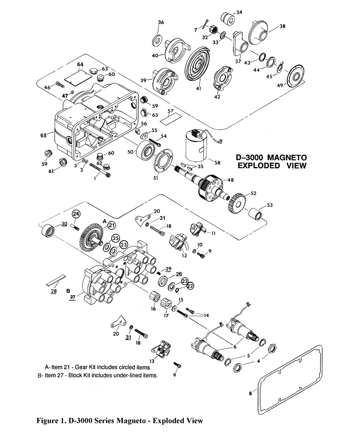
Recently, my airplane partner called to let me know that we had a magneto failure — there was no spark from the left mag. Our airplane has a Bendix dual magneto, and the mag had only about 300 hours since overhaul by a respected repair facility, so I was surprised to have a failure. I immediately put together what I thought was a comprehensive list of things to check to correct the problem. Here’s my diagnostic checklist in order of most likely to least likely source of the problem.
- The p-lead cap vibrated loose on the back of the mag and is shorting that side. This is an easy fix.
- The p-lead connection at the ignition switch worked loose and the p-lead shorted against a ground. This is also an easy fix, maybe with some blue Loctite to prevent a recurrence.
- The p-lead shorted to the ground, internal to our new ignition switch. This seems unlikely with a new TSOed Cessna ignition switch, but I guess any part can fail, even if it is new.
- A condenser in the mag shorted. I have never seen that happen, but I suppose it’s possible, or the wire to the points inside the mag might have chafed and shorted. This can be diagnosed by checking resistance from the coil lead to the case.
- The rubbing block on the points cam has worn so the points aren’t opening. This seems unlikely on an overhauled mag with less than 400 hours. The fix would require resetting points gap to re-time the internal timing on both sides.
- The points have eroded enough to not close. This is also unlikely on an overhauled mag. It would require installing a new set of points and changing out the condenser (since a bad condenser would be why the points failed). But we have spare condensers.
- The distributor rotor failed. That’s unlikely on an overhauled mag, but if a few rotor gear teeth broke off so the rotor isn’t turning, that would show up as a failure.
- The coil failed (cracked). Since the coils were replaced at mag overhaul, that isn’t likely. But we have spare coils. Coil failures usually start out intermittently because a break in the secondary wire will simply arc across the break for a while. In my experience, cracked coils work fine when cold but quit when the engine gets hot, which causes the coils to expand and widen the crack. This can be diagnosed by measuring resistance across the coil windings.
Running Through the Diagnostic List
With this checklist in hand, I went out to the hangar. I first verified that the p-lead connections were still tight. Then I disconnected the p-leads and verified that the wiring to the ignition switch was good and that the ignition switch properly grounded and isolated the p-leads at the appropriate switch positions.
Then I removed the magneto cover and visually inspected the distributor gears. They appeared to be intact and in time. I had my partner move the prop, and I could see the points opening and closing. I hooked a digital voltmeter across the points to verify. The point resistance went from near zero to open circuit just like it should.
opening and closing properly.
Next Step: The Bench Check
At this point, I felt I had ruled out all failure mechanisms except a bad coil, so I pulled the mag from the engine and took it to the bench to begin a teardown to replace a coil. Once the mag was on the bench, I did a couple more checks. I checked the points gap, which was at 0.012 (the spec is 0.016, so it had probably closed up since overhaul). I was checking coil resistance and happened to check point resistance to ground.
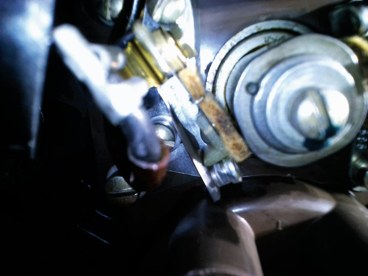
Looking at the mag in the airplane, I measured resistance across the points, so this was a process change. I was quite surprised to find that the left side points measured 35-40 ohms from the points base plate to ground. Aha! That was the smoking gun. Since the primary coil resistance is under one ohm, a 35-ohm resistance to ground from the mag points would reduce spark output by over 90%.
I removed the point blocks and found that the area under the points was a tad oily but didn’t look terribly corroded. There is a thin brass shim under the points plate that provides an electrical path from the plated plate to the magneto block mounting screw, which is the primary ground path on a Bendix D-3000 magneto. I debrided the plate and shim with a soft brass brush and then removed any residual oil traces by cleaning with denatured alcohol. I verified that the points-plate-to-ground resistance was under a tenth ohm and carefully reset both sets of points to 0.016 gap.
The Fix
At that point I figured that I was pretty much done. All that was left was reinstalling the mag and timing it to the engine. But not so fast! I had previously installed dual mags a couple times, but this one was giving me fits. I put it on several times but it wouldn’t time up. I reached out to our local master mechanic, Ray Meyer, for advice. Ray asked me if I had a magneto holding tool. “Why, no,” I replied. Ray generously lent me his tool and took a dual mag on the bench to show me how to use it. I returned to the hangar and had the engine timed up, plugs reinstalled, and run up an hour later.
The Explanation and Lessons Learned
It turns out that when the points are set to the proper gap, at the proper rotor rotation angle for installation, there is a lot of pressure from the rubbing blocks trying to turn the rotor. It’s almost impossible to keep the mag rotor from rotating out of time when mounting the mag on the engine. But with the mag-holding tool to secure a distributor gear, reinstalling the mag to the proper time was easy.
I learned three things on this job. First, there’s at least one more failure mode than I had thought of. Second, a special tool can be a big help. And third, it’s great to have knowledgeable friends.
THE DIAGNOSTIC PROCESS
This particular job involved a failed magneto, but the principles apply to virtually any diagnostic situation. By methodically following a list of possible causes of the failure and ruling them out one by one, from most likely to least likely, a mechanic will eventually uncover the source. As shown in this example, however, even a highly experienced mechanic may discover a previously unknown cause. But this information can be added to the checklist to improve the diagnostic process. One of the skills Jerry used in his engineering career is Root Cause and Corrective Action (RCCA). The principles used in RCCA are foundational to diagnosing and repairing mechanical failures in a systematic and efficient manner.
While most mechanical issues need to be diagnosed and repaired by a licensed A&P, plane owners can use the same process to develop a systematic approach to diagnosing owner-level issues.
TROUBLESHOOTING AN IN-FLIGHT EMERGENCY
One of the benefits of diagnostic troubleshooting is that it can be a lifesaver during an in-flight emergency. Tackling a problem using a logical process of elimination can help a pilot stay calm and in control, prevent wasted time, and come up with a solution faster and more effectively. For example, if a pilot suddenly lost all electrical power at night, it would be very helpful to have learned, practiced, and internalized the principles of RCCA so thoroughly that they can be immediately applied to handle this potentially life-threating situation.
AOPA (aopa.org) explains the proper response to this emergency on its website under Training & Safety > Online Learning > Emergency Procedures > Other Emergencies.
“An electrical failure at night or in IMC is a serious emergency. Troubleshoot the obvious first. If the cockpit suddenly went dark, did you accidentally hit the master switch? If the ammeter is showing a discharge (or a zero reading on a load-type ammeter), the alternator may have tripped offline. Follow POH procedures for a reset. If the issue can’t be resolved, start reducing electrical load to the essentials: Drop back to one radio and minimal navigation gear, shut down unnecessary lights, and turn off anything else that’s drawing power. Stay in VMC if possible. If it’s IMC, declare an emergency and divert.”
Jerry LeCroy was employed in aerospace engineering design and systems analysis for about 40 years, with the last 20 at Boeing. His work included spacecraft design, spacecraft propulsion, military aircraft, space science experiments, and commercial aircraft. During his final seven years, he focused on Boeing 787 systems design and certification.

