By Elizabeth Gibbs
When was the last time you thought about why your instruments are arranged the way they are? Often the only time it is thought about is when a pilot is looking to upgrade their instruments or rearrange them to a more pleasing layout.
Modern Cessna 172s are equipped with impressive G1000 “Glass Cockpit” screens, but it is more likely that many pilots who learned in the Cessna 172 learned with “steam gauges” in a standard six-pack layout with a center radio stack. When compared to the 172N, P, R, and early S models, older models have nonstandard layouts that seem to lack symmetry and purpose. When older models are purchased, owners often look at their jumbled instrument layout and consider how they can create that six-pack layout that they trained on.
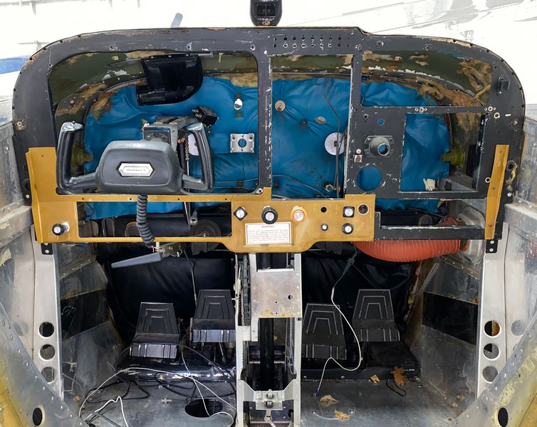
But the reason for these nonstandard layouts might be more complex than some owners realize. The original instrument panel came in three parts. The first was a plastic overlay, which revealed only the faces of the instruments and presented the pilot with a relatively pleasing and uncluttered view. Once the plastic overlay was pulled off (or broken off due to age and wear), most of the instruments are contained in an aluminum panel known as the shock panel. The shock panel is attached to the structure behind it using a set of rubber mounts, meant to isolate the sensitive instruments from the vibration of the aircraft. Instruments typically considered less sensitive, such as engine and temperature gauges, were often mounted directly to the structure behind the plastic. That structural piece is called the stationary panel. It is a part of the aircraft’s structure and, according to the Cessna 172 service manual, considered not ordinarily removable due to being directly secured to engine mount stringers and a forward fuselage bulkhead.
Over the many years of Cessna 172 production, the stationary panel has been redesigned several times, which creates many different nonstandard layouts through the early years. It is the stationary panel that defines the layout of the instruments, not the outer layers of the instrument panel. A redesign of the aluminum shock panel can sometimes yield slightly better results, but owners will often find it nearly impossible to achieve the look they want without running into the stationary panel structure behind.
Most of our in-depth, detailed articles are for members only. This article has been made available to all website visitors.
An Overview of Models
Early models of 172, from 1956 to 1958, took the design from earlier Cessna models, similar to the 170. The stationary panel was designed to be open around and above the yokes to allow for the various-sized instruments. Most of the instruments were positioned above the control wheels, while radios were below the control yokes in the lower panel, and both the shock panel and plastic overlay were one piece and contained all instruments.
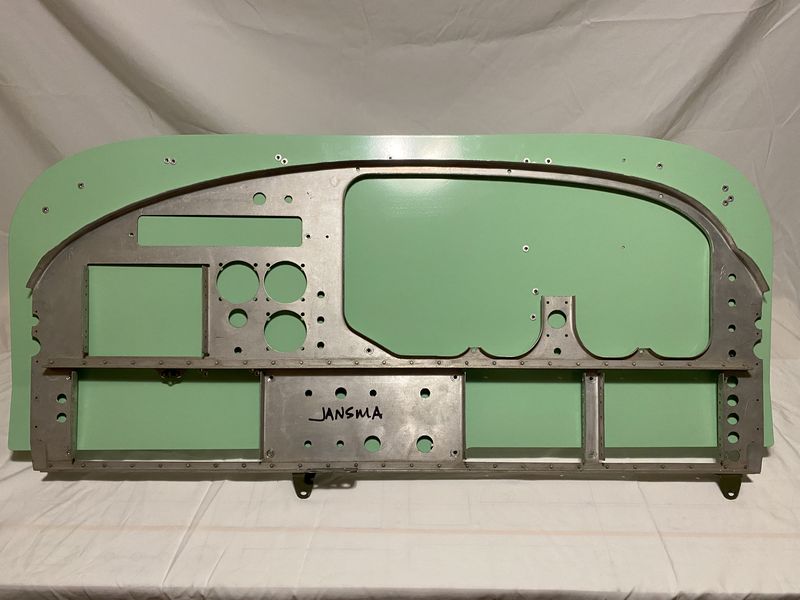
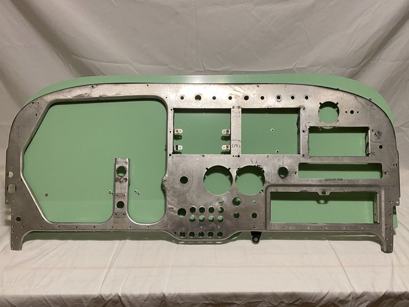
The 1959 172 and the 1960 172A panels held the same general shape, but most of the instruments were shifted to a shock panel that extended only from the left side to near the center. From there, the stationary panel housed most of the engine instruments. In all models 1960 and prior, instruments and radios were limited on placement due to the T shape of the control column, with a bar directly connecting the two control yokes behind the panel. (See Images 1 & 2).

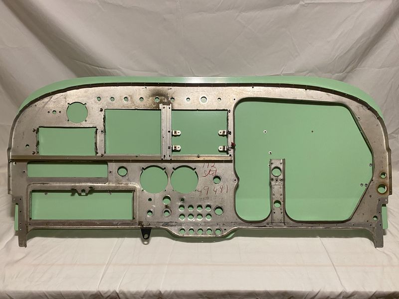
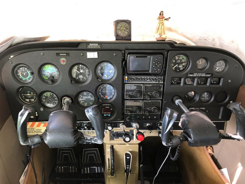
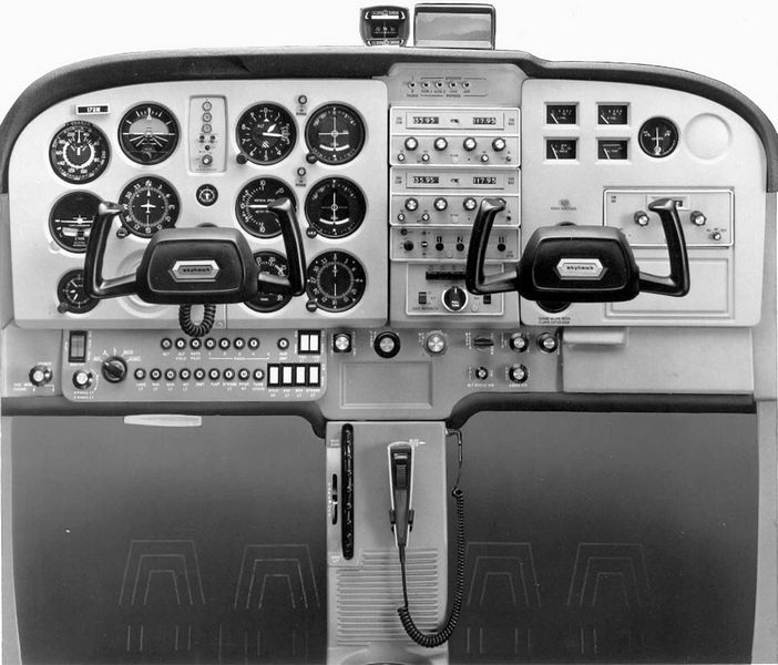
In 1961, with the introduction of the 172B, and continuing on through 1963 with the 172C and 172D, the stationary panel changed significantly and began to take on a more familiar shape. By moving the radio location from below the yokes to the two small bays in the center of the stationary panel, space below the control yoke was now utilized for flight instruments. This design changed allowed for three standard 3.125-inch instruments to be placed below the pilot-side yoke, and the remainder of the flight instruments to be positioned directly to the left and right of the yoke. Engine instruments were laid out throughout the remainder of the stationary panel, positioned around the radios. The radios were confined to two smaller stacks due to the continued use of the T bar for the control yokes. (See Images 3 & 4).
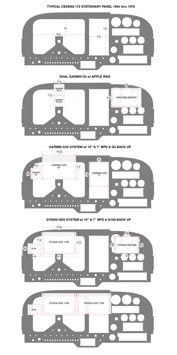
The 1964 172E changed the T bar into a U shape welded to a center column. This opened up the space needed for the center radio stack. The pilot-side shock panel was slightly redesigned again to move the three 3.125-inch instruments above the yoke in a column, and the other instruments were shifted to cluster around the control yoke to compensate. Switches, fuses, cabin air, and heat controls were moved to the area below the pilot’s control yoke after giving up their previous positions to accommodate for the radio stack. To create space for this, the solution was to build up the control yoke support into a tapered area that created room for the displaced switches and controls. All engine instruments were clustered on the right-side panel, built into the stationary panel. Additionally, an area was added to the far right of the panel for more radio equipment to be installed. (See Diagram B).
Between 1965 and 1970, minimal changes were made to the panel design. Fuses, switches, and air controls were shuffled around until they found their home solely in the lower panel. By 1967 the tapered control yoke support was empty, and Cessna opted to cover that empty area completely with a plastic panel on these models, hiding what is essentially unusable space. (See Image 5).
A big jump in panel design came with the 1971 172L (See Diagram E, Images 6 & 7). In an attempt to do away with as much unusable space as possible, the stationary panel was built with an open area for the pilot’s side panel with the control yoke support narrowed. The panel could now accommodate four rows of three instruments, however, due to the curve of the panel the far-left row could only accommodate two 3.125-inch instruments and one 2.25-inch instrument. The center area above the yoke was still too small at this point to house two 3.125-inch instruments, so this became the home of built-in marker beacon lights and a suction gauge. The right-side stationary panel has an opening on the top section, where a plate would be screwed on housing fuel and temperature gauges. On the far-right side, the area was enlarged to allow for more auxiliary radio space.
This was the last iteration of the nonstandard layouts, and it lasted until late 1975, when a fundamental change began with the 172M, serial number 17265685. At this time, Cessna opted to lower the control yokes to gain more space within the panel area. Lowering the yokes nearly 1.5 inches, as well as opening up the edges of the stationary panel slightly, finally gave the clearance needed to fit two full-sized 3.125-inch instruments above the controls. At last, after 19 years, the Cessna 172 was able to fit a standard six-pack layout.
Taking the time to understand the structure behind the plastic overlay is an important first step in understanding which of the many avionics upgrade solutions are right for your model of Cessna.
Most of our in-depth, detailed articles are for members only. This article has been made available to all website visitors.
Faced With a Problem
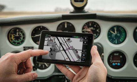
One of, if not the most tantalizing of modern avionics upgrades available today is the glass cockpit. There are many versions on the market, but the current most popular two are the Garmin G3X Touch and the Dynon Skyview HDX. Both offer smaller 7-inch displays depending on the system, but the larger 10-inch Primary Flight Displays are often the more desirable of the two options. These screens can be integrated with GPS units, radios, transponders, and autopilots to create a seamless user experience. Both systems are STCed and include all models of Cessna 172 in their approved models list.
However, there is a problem when it comes to installing these larger 10-inch screens in older models. Prior to pulling apart any part of the instrument panel, the owner of a pre-late-1975 Cessna 172 could print out the manufacturer-provided templates, hold them up to the plastic overlay, and find that the larger screens appear to fit with minimal adjustments. Once the plastic overlay and shock panel are both removed, another story becomes evident. In Cessna 172 models without the standard six pack, in which the stationary panel does not allow for two 3.125-inch instruments above the control yoke, the larger screens will not fit. In order to make them fit, significant portions of the stationary panel must be cut away. In some models, metal must be completely removed all the way to the glare shield. (See Diagrams D, F, G, and H).
Other common modifications that involve removal of a significant amount stationary panel material also include any additional Multi Function Display (MFD) screens or iPads on the right side of the panel.
Remember that the stationary panel is a structural part, attached to engine mount stringers and a forward fuselage bulkhead. The stationary panel’s primary job is to carry the load of your instruments and avionics in all phases of flight, including straight-and-level cruise flight and during all flight maneuvers including stalls, stall recovery, steep turns, etc. It is difficult to ascertain exactly how much additional load the stationary bears beyond the instruments, but it is likely that it bears at least some fuselage load and possibly even forward landing-gear load. Considerations must be taken during any new avionics or instrument installations to minimize any actions that could compromise structural integrity.
Section 1.3 of Dynon’s Skyview HDX installation manual reads:
“Airplanes identified on the Supplemental Type Certificate (STC) Approved Model List (AML) have been determined to meet a minimum required configuration for applicability of the STC. However, as some airplanes may have been modified over the years, it may be difficult to use the information in this manual to completely substantiate the installation in compliance with the STC. It is the installer’s responsibility to make the final determination of applicability for each individual aircraft.”
Avionics manufacturers have taken care to ensure that their products will be able to perform all the intended functions in each model on the approved model list, but they have also acknowledged that over the years, many different modifications may have occurred, making it difficult to know if their system will fit or not. Keep in mind that the STC also covers the smaller screens as well. The 7-inch Dynon Skyview HDX screen will fit in many older models that the 10-inch will not and perform all the same functions.
The avionics shop that is installing the system has the final say as to whether the systems will fit in the aircraft, but take caution when speaking to a shop that appears to have little regard for the stationary panel as a structural part. In recent conversations with FAA representatives from my local Flight Standards District Office (FSDO), I was astonished to hear that there are shops that operate under the belief that the stationary panel is not a structural part. In some aircraft this may be true, but it is not so in the case of the Cessna 172, especially not in the eyes of the FAA.
Looking Forward
It is not impossible for owners to install their dream avionics in their legacy airplane. It is likely that the only way to keep the aging fleet of 172s going is to update them and maintain them. However, by perpetuating these misunderstandings about how to deal with modifying the stationary panel, the future airworthiness of these airplanes may be at risk. It is not impossible to install a 10-inch screen in an older model of 172, but a few extra steps may need to be taken to ensure that the structural integrity remains intact. Usually, a few extra steps equal a few extra dollars, but why cut corners when it comes to the structure of your airplane?
The FAA has outlined regulations for how to deal with making modifications to stationary panels. AC 43.12-2B, Section 203, Subsection A states the following:
“The stationary instrument panel in some aircraft is part of the primary structure. Prior to making any additional ‘cutouts’ or enlargements of an existing ‘cutout,’ determine if the panel is part of the primary structure. If the panel is structural, make additional ‘cutouts’ or the enlargement of existing ‘cutouts’ in accordance with the aircraft manufacturers’ instructions, or substantiate the structural integrity of the altered panel in a manner acceptable to the Administrator.”
If the stationary panel needs to be altered to install a larger display, or even to accommodate that six pack, then those alterations can be made if it is done in a manner that maintains the structural integrity to the same standards and is documented in the logbooks. These are considered major alterations, which may require the need to involve a Designated Engineering Representative (DER). The DER can assist in determining what additional supports and modifications are needed to ensure structural integrity of the airframe in maintained. Once modifications are approved by the DER, they will issue a form 8110-3 detailing the modification, and it will be added to your aircraft’s logbook along with a 337.
Looking forward, the FAA is working to provide STCed solutions that could allow for the installation of avionics that require a larger area within the stationary panel. These products are under careful consideration to ensure they provide the same or better structural integrity to the airframe while allowing for 10-inch displays or standard six-pack instrument layouts.
If you have any further questions prior to installing new avionics in your aircraft, do not hesitate to contact your local FSDO and ask to speak with someone regarding this matter. Also, read AC 43.13-2 to gain a further understanding of the recommended considerations for structural parts as well as avionics installations. Beware when you see aircraft owners on social media and YouTube openly advertising installations of larger primary flight displays (PFD) screens in Cessna 172 models prior to late 1975. Make sure that you do your own research to know what proper measures can be taken to ensure that the structural integrity of your aircraft is maintained.
Download a large PDF of the diagrams in this article. Click here.


