 Under the Cowling

“BREAKING UP” with your Radio?
Not so fast…your antenna might be the real problem!
Aircraft owners typically invest a lot of money in avionics equipment for their planes, and other than an engine overhaul, there is usually no greater expense for owners than the time and money spent on radio upgrades and repairs. Some of the most important – though often overlooked – components of these systems are the antennas through which information used by these units is transmitted and received. In fact, radio transmission problems, background noise, erratic signal reception, and a host of other squawks blamed on the radio units, are actually caused by an antenna malfunction.
Obviously, airplane antennas take a lot of abuse. Not only are they subjected to strong winds on each and every flight, but they get pummeled by bugs during the summer months as well. Of course, rain, snow, and sleet take their toll too, eventually causing erosion on the leading edges. Antennas are also subject to vibration, depending on where they are mounted and how securely the antenna base is fastened to the airframe. This can lead to antenna cracks or delamination. Belly-mounted antennas face even more abuse, as they inevitably accumulate a layer of sludge from the engine breather and are more likely to get chipped from debris during ground operations.
One of the biggest causes of degraded performance is corrosion that forms between the aircraft skin and the antenna base. Antennas need a negative electrical ground in order to operate correctly. Different antennas ground in different ways. Some antennas use a bond between the antenna base and the airframe skin to ground the antenna to the airframe itself. Others have a dedicated ground wire that is run to a grounding station.
Antennas that use the aircraft skin as a ground need a clean surface between the base and skin; otherwise the increased electrical resistance causes poor reception and transmission from the antenna. Some antennas that use the skin as a ground also use a special gasket that is impregnated with a metal mesh that helps create a good electrical bond with the skin. The skin must be clean and free of paint to achieve a good bond.
In order to function properly, an antenna must have a good electrical ground and a good connection to the radio itself.
The VHF transceiver installed in most general aviation airplanes operates within a frequency range of 118.00 to 136.975 MHz. The term ‘frequency’ refers to the number of wavelengths that are transmitted or received per second. Radio signals are transmitted in waves, with the wavelength being the distance between two consecutive wave peaks. A frequency of 123.90 mega-hertz means that one hundred twenty three million nine hundred thousand waves per second are being transmitted or received. All of this information goes through the antenna, where it converts electric power into radio waves or vice versa—depending on whether it is receiving or transmitting.
Antenna Types
- Communication antennas are generally located on the top and bottom of the fuselage. They are usually long single pole antennas that have a wide base and are swept back.
- Navigation antennas are typically one of three types:
- “Cat whisker” type – mounted near the upper part of the vertical stabilizer and consist of two single metal rods that are swept back
- “V” type – mounted on top of the fuselage (Beechcraft and some Pipers)
- “Dual blade” type – mounted on each side of the vertical stabilizer. Dual blade nav antennas give the best performance (better reception) and are also more aerodynamically efficient, causing very little drag.
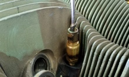
- Marker beacon antennas are mounted on the belly and are typically either an elongated thick blade type or a long metal rod that comes down slightly and is bent back, parallel to the belly.
TIP: These have a wire and clamp that can be adjusted to fine-tune sensitivity. Loosening the clamp and moving the wire forward or aft adjusts the sensitivity of the marker beacons. It’s best to mark the original location so you’ll know where you originally started, as small movements make big adjustments.
- GPS Antennas – require a direct line of sight with the satellites they receive signals from, so they are typically mounted on the top of the fuselage. Communication antennas can cause interference with GPS antennas, so they should be mounted as far from each other as practicable.
TIP: All antennas should be mounted at least five feet from strobe lights, power supplies, or alternators because of the noise induced by these items. Antennas should also be mounted a proper distance from each other—36 inches apart (or more if practical) is a good distance to avoid interference.
Troubleshooting your Antenna’s Coax Cable
When troubleshooting an existing installation, it is helpful to check the continuity and resistance through the coax from end to end to be sure it is electrically sound. A megger meter, which actually sends voltage through the center conductor, can be used to see if the coax is shorted to ground anywhere.
Both ends of the coax have to be disconnected so that neither the radio nor the antenna is damaged before the megger is used. It tests for any breaks in the insulation of the coax that would allow current to escape from the center conductor to the wire braided shielding on the outside. The coax should be free of sharp bends and should not be routed adjacent to other coax cables to prevent interference.
TIP: The coax cable used to connect certain antennas to the radio unit should be the 50-ohm RG-58 coax used for airplanes. The type used for television and home (usually 72-ohm) will not work properly.
Anytime an airplane is having radio issues, especially communication issues such as static or poor transmission or reception, thoroughly checking the antenna, coax, and connections before replacing an expensive piece of avionics equipment can save a lot of time and money.


