Under the Cowling
Airplane Cable Tensions and Control Surface Rigging
The flight control system in most airplanes consists of a series of bellcranks and rods that connect the flight control surface (aileron, rudder, or elevator) to a series of cables that run through the wings and fuselage to the yoke or stick. These cables transmit the motion applied by the pilot at the stick/yoke to the control surface.
Just as an automobile needs occasional alignments and adjustments to make it steer properly and track straight without pulling left or right, an airplane control system must be adjusted at times to ensure that the airplane flies straight and level.
When checking rigging and tension in a flight control system, the first step is to put the stick/yoke in a neutral position, or the position recommended by the manufacturer for the particular system being adjusted.
The ailerons are usually the most time-consuming system to rig. When rigging the ailerons, a long, straight piece of metal, about the size of a yardstick, is first placed across the tops of the control wheels and secured in place to keep the wheels neutralized together.
Next, with the flaps in the retracted position, look at the position of the trailing edges of both ailerons in relation to the trailing edges of the flaps. When properly adjusted, most planes will have a certain amount of “droop” where the trailing edges of both ailerons hang down a little below the trailing edges of both flaps.
Before any adjustments are made, the next step is to check the cable tensions to determine baseline readings.
Aileron systems actually have three cables: two cables connect the left and right bellcranks to the control wheels, and a third, “carry–through” cable connects the two bellcranks to each other. A tensiometer is used to check the tension on each cable. Most cables are 1/8-inch while trim tab cables are usually 1/16-inch in diameter. Tensiometers have different blocks that are inserted for different cable sizes. They also have a correction chart based on the cable size that gives an actual reading for the indicated reading.
Note: Tensiometers are relatively expensive ($800 to $900) and must be calibrated occasionally, so it may be best to rent or borrow one from a shop. They are calibrated by hanging weights from a cable in a vertical plane and measuring the tension on the cable and comparing it to the suspended weight.
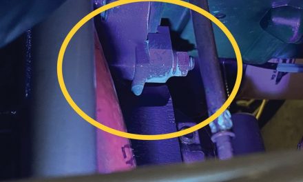
The tensiometer gives the most accurate reading for a cable tension when the tension is measured along a freestanding section of the cable, away from pulleys or turnbuckles. Turnbuckles are threaded internally with one side having left-hand thread and the other having right-hand thread. The cables have threaded ends that are swedged onto the cable itself with a hole to accommodate safety wire. The turnbuckle has a circle etched around the end that has left-hand thread and is secured with .041” safety wire or turnbuckle clips that slide in and lock the barrel so that it can’t turn.
When making tension adjustments, the cables need to be held in place so they don’t twist as the turnbuckle is rotated. This can be accomplished by inserting a bent welding rod or coat hanger through the holes in both cable ends. The turnbuckle can then spin without twisting the cables.
As the tension is adjusted on one cable, it changes the tension on the other cables and the control surface position. (Follow the steps recommended by the manufacturer for tensioning each cable in the correct order).
Once the tensions are set, the droop can be adjusted by lengthening or shortening the length of the rod connecting the aileron to the bellcrank. The rod ends are threaded and most have small holes in which a piece of safety wire can fit. These ‘witness holes’ ensure that the rod end is not backed off too far. The safety wire should not pass through the hole because of contact with the rod itself. If it does pass through, the rod-end is backed off too far and will have to be screwed back in and adjustments will have to be made on the other end.
With the tensions and droop set, the straight edge can be removed from the control wheels. Check the ailerons for freedom of movement and make sure that they have a full range of travel. The control surface should move freely from stop-to-stop and not bind in any way. The amount of travel a particular control surface has is measured with a prop protractor. This device has a circular scale and an adjustable bubble level. It is placed on top of the control surface and the level is set to zero with the control surface in the neutral position. The surface is then fully deflected in each direction with the measurements being read at the “full up” and “full down” positions. The surface must fall within an acceptable range of up or down travel. The ailerons will have more “up” travel to overcome adverse yaw produced by the lowered aileron on the other side.
Once everything is set as it should be, all turnbuckles should be secured and all hardware installed. Lubricate and inspect all pulleys as the controls are moved to ensure that they aren’t “frozen.”
The elevator and rudder systems are just as critical as the aileron system, but usually easier to rig because they have only one surface. A properly rigged airplane simply flies better— just like a properly aligned car is easier to drive.
