I guess many owners change their own oil and filter. It turns out that it’s a large cost savings over paying the local shop to do the job. Changing the oil was satisfying to me, knowing it was done right, the oil sample was taken correctly, and the sample was mailed to the lab promptly. However, changing the oil filter in my old Cessna 172 was not part of job satisfaction. Just to get my hand onto the filter required snaking around wires, oil lines, and cables. To make matters worse, the engine and filter were hot, as was the oil that poured out as I backed the filter off the filter adapter. The oil ran down the wires, oil lines, lower firewall, and strut before finally wetting the front wheel pant. All this resulted in spending more time cleaning up the mess than changing the oil and filter.
Source a Kit
One recent hot Texas day, I spotted a really nice 1954 Cessna 170B at the shop across the taxiway. An annual was underway and, being partial to the early taildraggers, I had to check out this classic. This buggy had an IO-360 Lycoming conversion with constant-speed prop. I was really impressed and envious. A remote oil filter had been installed down low on the left side of the firewall. I thought to myself, The remote filter would be a great addition on my C172. It would make changing the filter much easier and much less messy.
So, I Googled “Aircraft Remote Oil Filter,” and Airwolf appeared. Further digging on the Airwolf site revealed that it has kits for most, if not all, applications of Lycoming and Continental engines in Cessnas. I contacted Airwolf and ordered the filter. Airwolf offered to take it to AirVenture so I could pick it up at their booth and save the shipping cost. So I did and brought the kit home and began the installation at oil-change time.
The Airwolf installation instructions were straightforward and, given my A&P experience, they seemed simple. However, an owner should not attempt this installation without an A&P’s supervision, because the installation is considered a major engine alteration. Any major alteration has to be signed off and logged by an A&P mechanic. The remote oil filter kit comes with an STC, but an IA-approved FAA Form 337 is required. After an A&P/IA signs off on the form, copies are placed in the aircraft logs and sent to the FAA in Oklahoma City.
The Installation Process
The installation described in this article was completed on a Lycoming O-320-E2D, which was the standard engine for the Cessna 172 I thru M. I chose the Airwolf kit because of the clean install I witnessed on the Cessna 170 and the professional service they provided.
The installation described in this article was completed on a Lycoming O-320-E2D, which was the standard engine for the Cessna 172 I thru M. I chose the Airwolf kit because of the clean install I witnessed on the Cessna 170 and the professional service they provided.
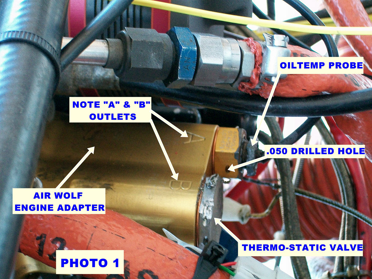
The first step is to remove the original oil filter and oil filter adapter from the accessory case. Remove the thermostatic bypass valve and oil temperature fitting from the original oil filter adapter, and then install them into the new engine fitting using the new copper gaskets included in the kit. On my airplane, the original thermostatic bypass valve was safety-wired to the original oil filter adapter. However, the new Airwolf engine adapter was not drilled for safety wire, nor was the new temperature probe fitting. So I drilled a .050-inch hole in the temperature probe fitting so the original thermostatic bypass valve could be safety-wired to the temperature probe fitting. I didn’t want to rely just on torque for these fittings, as they’re critical to your health (See Photo 1).
Install the new copper gaskets, supplied in the kit, on the thermostatic bypass valve and temperature probe fittings. Torque the fittings as required and safety-wire them together. Install the two AN swivel fittings into the engine adapter, but do not tighten at this time. Install the new engine adapter with two ¼-inch nuts just to hold it in place. Tighten the nuts hand tight. This temporary installation will be used to position and determine the length of the new oil lines. The swivel fittings cannot be properly tightened when installed on the engine, due to the location and angle of the fittings. The final installation will be discussed later
Location, Location, Location
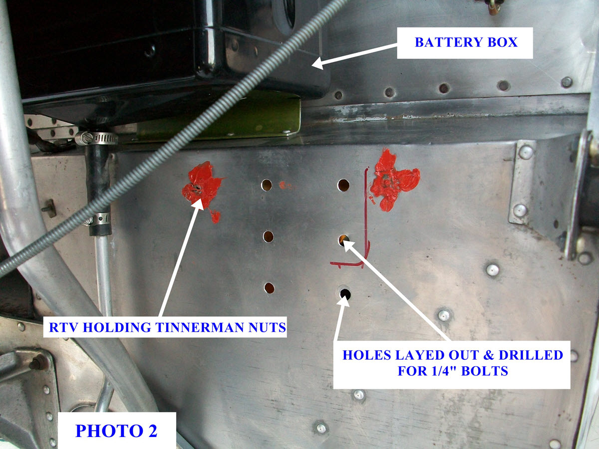
I selected a good location for the new oil filter below the battery box (See Photo 2). The installation requires six AN-4 (¼-inch) bolts through the firewall with lock nuts and washers on the inside. It’s very important to make sure that the selected locations for the bolts are accessible on the inside of the firewall and that they won’t interfere with other stuff on the firewall or under the instrument panel.
For me, getting access to the inside firewall wasn’t easy. The left side kick panel had to be removed, the carpet rolled back, the rudder pedal cover removed, and several difficult sheet-metal screws through the firewall removed. The upper screws held the fiberglass insulation against the inside surface of the firewall. Tinnerman nuts held the screws on the outside surface, and I applied red RTV to hold the Tinnerman nuts so they would stay in place when the screws were adapter. Then I held the filter housing and mounting plate at the selected firewall location and marked the six holes.
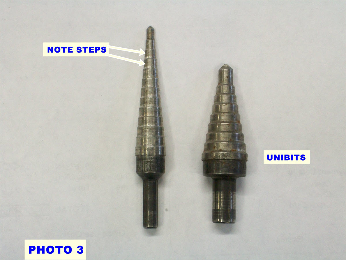
Carefully center punch each hole location. Don safety glasses and drill a #30 pilot hole. Enlarge the holes with a Unibit (See Photo 3). The Unibit is ideal for drilling sheet metal. It won’t grab like a twist drill and won’t produce a sharp burr. Enlarge the holes to the next step beyond the ¼-inch step. This will allow all six bolts to be installed, even if there are errors when locating and drilling the holes.
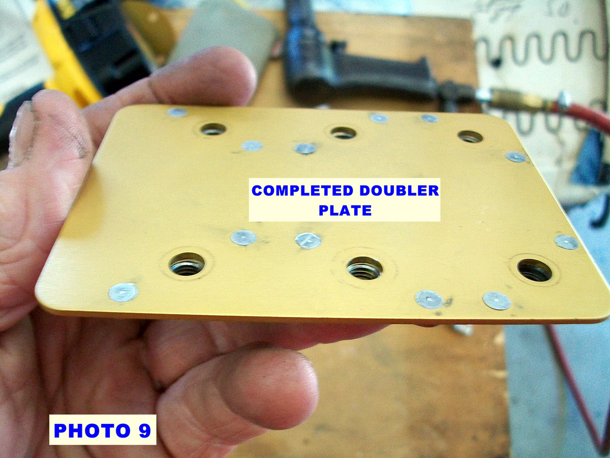
Assemble and Install Doubler Plate
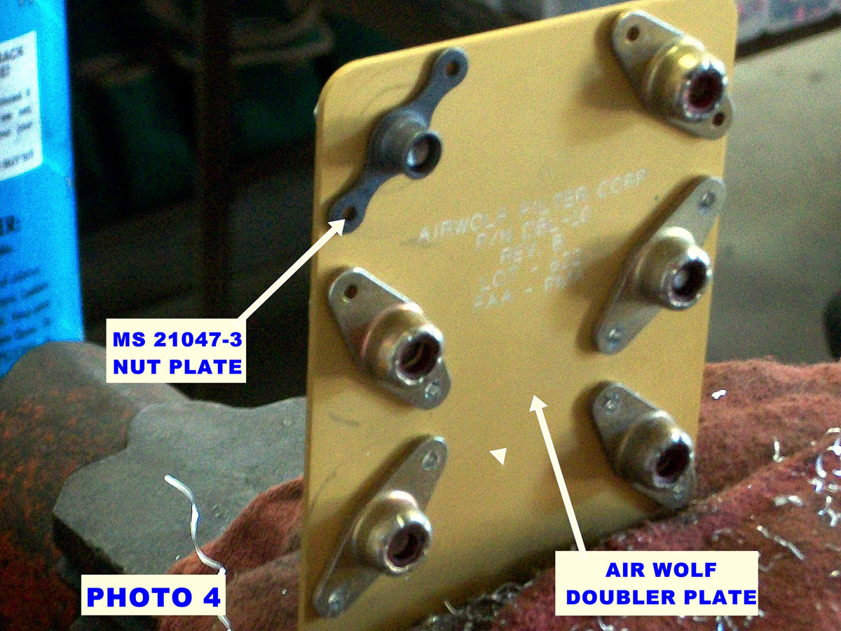
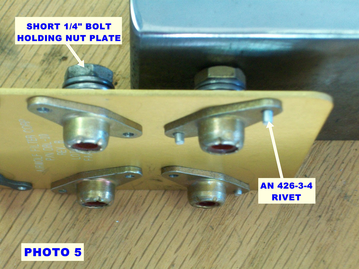
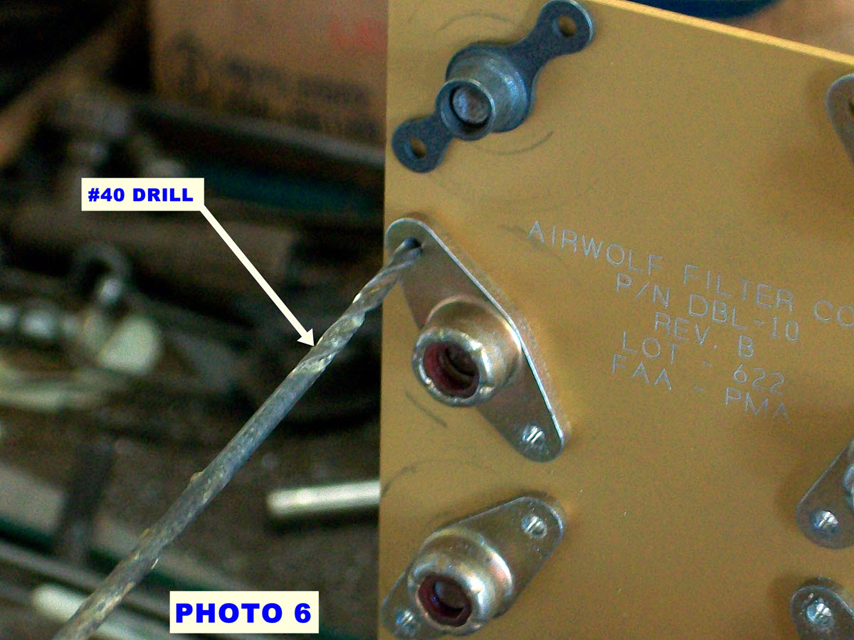
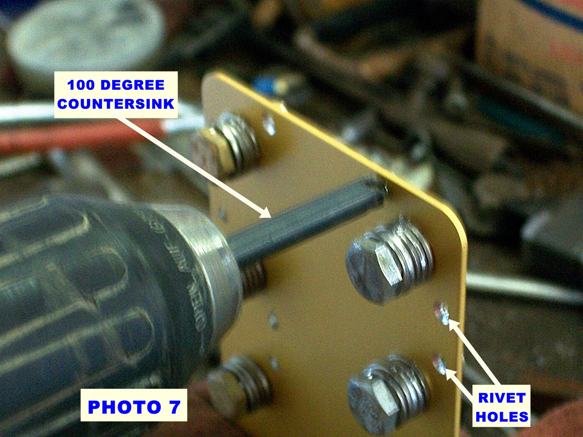
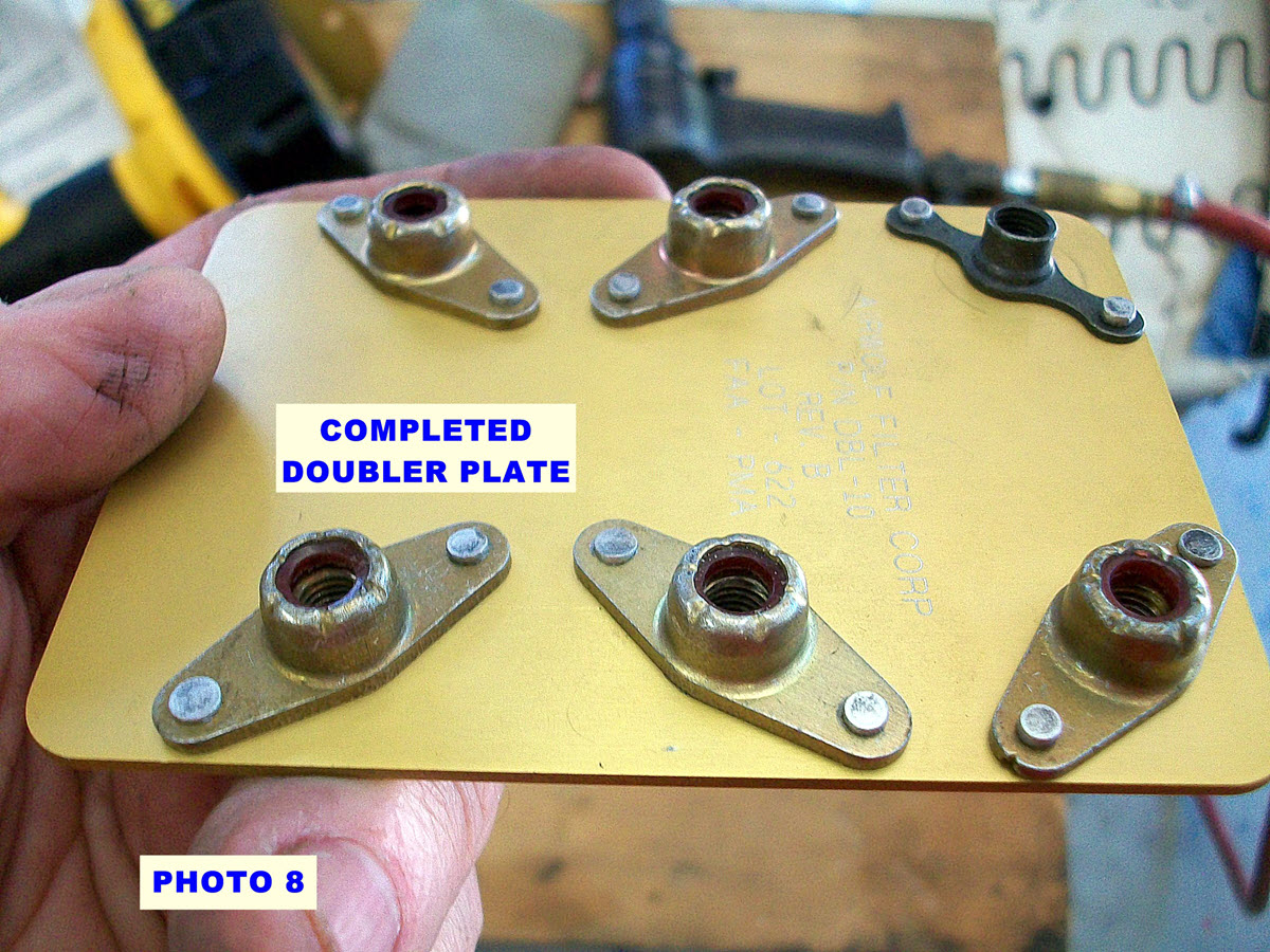
The Airwolf installation requires a doubler plate on the inside of the firewall with through bolts, washers, and lock nuts to secure the new oil filter adapter. Lying on my back and installing washers and nuts seemed difficult. So I modified the doubler plate by adding nut plates (See Photo 4). Each nut plate is held in place on the doubler plate with short ¼-inch bolts and flat washers. Tighten the bolts so that the nut plates will not move (See Photo 5). Drill each nut plate rivet hole through the doubler with a #40 bit and countersink the opposite side with a small 100-degree countersink tool. Rivet each nut plate to the doubler using AN 426-3-4 rivets (See Photos 6-9).
Have a website login already? Log in and start reading now.
Never created a website login before? Find your Customer Number (it’s on your mailing label) and register here.
JOIN HERE
Still have questions? Contact us here.
